Global Positioning System
The Global Positioning System (GPS) is a space-based satellite navigation system that provides location and time information in all weather conditions, anywhere on or near the Earth where there is an unobstructed line of sight to four or more GPS satellites.[1]
The GPS project was developed in 1973 to overcome the limitations of previous navigation systems,[2] integrating ideas from several predecessors, including a number of classified engineering design studies from the 1960s. GPS was created and realized by the U.S. Department of Defense (DoD) and was originally run with 24 satellites. It became fully operational in 1995.
Bradford Parkinson, Roger L. Easton, and Ivan A. Getting are credited with inventing it.
Advances in technology and new demands on the existing system have now led to efforts to modernize the GPS system and implement the next generation of GPS III satellites and Next Generation Operational Control System (OCX).[3]
Announcements from Vice President Al Gore and the White House in 1998 initiated these changes. In 2000, the U.S. Congress authorized the modernization effort, GPS III.
In addition to GPS, other systems are in use or under development. The Russian Global Navigation Satellite System (GLONASS) was developed contemporaneously with GPS, but suffered from incomplete coverage of the globe until the mid-2000s.[4]
There are also the planned European Union Galileo positioning system, Indian Indian Regional Navigational Satellite System and Chinese Compass navigation system.
Basic concept of GPS
A GPS receiver calculates its position by precisely timing the signals sent by GPS satellites high above the Earth. Each satellite continually transmits messages that include
- the time the message was transmitted
- satellite position at time of message transmission
The receiver uses the messages it receives to determine the transit time of each message and computes the distance to each satellite using the speed of light. Each of these distances and satellites' locations defines a sphere. The receiver is on the surface of each of these spheres when the distances and the satellites' locations are correct. These distances and satellites' locations are used to compute the location of the receiver using the navigation equations. This location is then displayed, perhaps with a moving map display or latitude and longitude; elevation or altitude information may be included, based on height above the geoid (e.g. EGM96).
Basic GPS measurements yield only a position, and neither speed nor direction. However, most GPS units can automatically derive velocity and direction of movement from two or more position measurements. The disadvantage of this principle is that changes in speed or direction can only be computed with a delay, and that derived direction becomes inaccurate when the distance travelled between two position measurements drops below or near the random error of position measurement. GPS units can use measurements of the doppler shift of the signals received to compute velocity accurately.[52] More advanced navigation systems use additional sensors like a compass or an inertial navigation system to complement GPS.
In typical GPS operation, four or more satellites must be visible to obtain an accurate result. Four sphere surfaces typically do not intersect.[a] Because of this, it can be said with confidence that when the navigation equations are solved to find an intersection, this solution gives the position of the receiver along with the difference between the time kept by the receiver's on-board clock and the true time-of-day, thereby eliminating the need for a very large, expensive, and power hungry clock. The very accurately computed time is used only for display or not at all in many GPS applications, which use only the location. A number of applications for GPS do make use of this cheap and highly accurate timing. These include time transfer, traffic signal timing, and synchronization of cell phone base stations.
Although four satellites are required for normal operation, fewer apply in special cases. If one variable is already known, a receiver can determine its position using only three satellites. For example, a ship or aircraft may have known elevation. Some GPS receivers may use additional clues or assumptions such as reusing the last known altitude, dead reckoning, inertial navigation, or including information from the vehicle computer, to give a (possibly degraded) position when fewer than four satellites are visible.[53][54][55]
Structure[edit]
The current GPS consists of three major segments. These are the space segment (SS), a control segment (CS), and a user segment (US).[56] The U.S. Air Force develops, maintains, and operates the space and control segments. GPS satellites broadcast signals from space, and each GPS receiver uses these signals to calculate its three-dimensional location (latitude, longitude, and altitude) and the current time.[57]
The space segment is composed of 24 to 32 satellites in medium Earth orbit and also includes the payload adapters to the boosters required to launch them into orbit. The control segment is composed of a master control station, an alternate master control station, and a host of dedicated and shared ground antennas and monitor stations. The user segment is composed of hundreds of thousands of U.S. and allied military users of the secure GPS Precise Positioning Service, and tens of millions of civil, commercial, and scientific users of the Standard Positioning Service (see GPS navigation devices).
Space segment[edit]


The space segment (SS) is composed of the orbiting GPS satellites, or Space Vehicles (SV) in GPS parlance. The GPS design originally called for 24 SVs, eight each in three approximately circular orbits,[58] but this was modified to six orbital planes with four satellites each.[59] The six orbit planes have approximately 55° inclination (tilt relative to Earth's equator) and are separated by 60° right ascension of the ascending node (angle along the equator from a reference point to the orbit's intersection).[60] The orbital period is one-half a sidereal day, i.e., 11 hours and 58 minutes so that the satellites pass over the same locations[61] or almost the same locations[62] every day. The orbits are arranged so that at least six satellites are always within line of sight from almost everywhere on Earth's surface.[63] The result of this objective is that the four satellites are not evenly spaced (90 degrees) apart within each orbit. In general terms, the angular difference between satellites in each orbit is 30, 105, 120, and 105 degrees apart which sum to 360 degrees.
Orbiting at an altitude of approximately 20,200 km (12,600 mi); orbital radius of approximately 26,600 km (16,500 mi), each SV makes two complete orbits each sidereal day, repeating the same ground track each day.[64] This was very helpful during development because even with only four satellites, correct alignment means all four are visible from one spot for a few hours each day. For military operations, the ground track repeat can be used to ensure good coverage in combat zones.
As of December 2012[update],[65] there are 32 satellites in the GPS constellation. The additional satellites improve the precision of GPS receiver calculations by providing redundant measurements. With the increased number of satellites, the constellation was changed to a nonuniform arrangement. Such an arrangement was shown to improve reliability and availability of the system, relative to a uniform system, when multiple satellites fail.[66] About nine satellites are visible from any point on the ground at any one time (see animation at right), ensuring considerable redundancy over the minimum four satellites needed for a position.
Control segment[edit]

The control segment is composed of
- a master control station (MCS),
- an alternate master control station,
- four dedicated ground antennas and
- six dedicated monitor stations
The MCS can also access U.S. Air Force Satellite Control Network (AFSCN) ground antennas (for additional command and control capability) and NGA (National Geospatial-Intelligence Agency) monitor stations. The flight paths of the satellites are tracked by dedicated U.S. Air Force monitoring stations in Hawaii, Kwajalein Atoll, Ascension Island, Diego Garcia, Colorado Springs, Colorado and Cape Canaveral, along with shared NGA monitor stations operated in England, Argentina, Ecuador, Bahrain, Australia and Washington DC.[67] The tracking information is sent to the Air Force Space Command MCS at Schriever Air Force Base 25 km (16 mi) ESE of Colorado Springs, which is operated by the 2nd Space Operations Squadron (2 SOPS) of the U.S. Air Force. Then 2 SOPS contacts each GPS satellite regularly with a navigational update using dedicated or shared (AFSCN) ground antennas (GPS dedicated ground antennas are located at Kwajalein, Ascension Island, Diego Garcia, and Cape Canaveral). These updates synchronize the atomic clocks on board the satellites to within a few nanoseconds of each other, and adjust the ephemeris of each satellite's internal orbital model. The updates are created by a Kalman filter that uses inputs from the ground monitoring stations, space weather information, and various other inputs.[68]
Satellite maneuvers are not precise by GPS standards. So to change the orbit of a satellite, the satellite must be marked unhealthy, so receivers will not use it in their calculation. Then the maneuver can be carried out, and the resulting orbit tracked from the ground. Then the new ephemeris is uploaded and the satellite marked healthy again.
The Operation Control Segment (OCS) currently serves as the control segment of record. It provides the operational capability that supports global GPS users and keeps the GPS system operational and performing within specification.
OCS successfully replaced the legacy 1970s-era mainframe computer at Schriever Air Force Base in September 2007. After installation, the system helped enable upgrades and provide a foundation for a new security architecture that supported the U.S. armed forces. OCS will continue to be the ground control system of record until the new segment, Next Generation GPS Operation Control System[3] (OCX), is fully developed and functional.
The new capabilities provided by OCX will be the cornerstone for revolutionizing GPS's mission capabilities, and enabling[69] Air Force Space Command to greatly enhance GPS operational services to U.S. combat forces, civil partners and myriad domestic and international users.
The GPS OCX program also will reduce cost, schedule and technical risk. It is designed to provide 50%[70] sustainment cost savings through efficient software architecture and Performance-Based Logistics. In addition, GPS OCX expected to cost millions less than the cost to upgrade OCS while providing four times the capability.
The GPS OCX program represents a critical part of GPS modernization and provides significant information assurance improvements over the current GPS OCS program.
- OCX will have the ability to control and manage GPS legacy satellites as well as the next generation of GPS III satellites, while enabling the full array of military signals.
- Built on a flexible architecture that can rapidly adapt to the changing needs of today's and future GPS users allowing immediate access to GPS data and constellations status through secure, accurate and reliable information.
- Empowers the warfighter with more secure, actionable and predictive information to enhance situational awareness.
- Enables new modernized signals (L1C, L2C, and L5) and has M-code capability, which the legacy system is unable to do.
- Provides significant information assurance improvements over the current program including detecting and preventing cyber attacks, while isolating, containing and operating during such attacks.
- Supports higher volume near real-time command and control capabilities and abilities.
On September 14, 2011,[71] the U.S. Air Force announced the completion of GPS OCX Preliminary Design Review and confirmed that the OCX program is ready for the next phase of development.
The GPS OCX program has achieved major milestones and is on track to support the GPS IIIA launch in May 2014.
User segment[edit]

The user segment is composed of hundreds of thousands of U.S. and allied military users of the secure GPS Precise Positioning Service, and tens of millions of civil, commercial and scientific users of the Standard Positioning Service. In general, GPS receivers are composed of an antenna, tuned to the frequencies transmitted by the satellites, receiver-processors, and a highly stable clock (often a crystal oscillator). They may also include a display for providing location and speed information to the user. A receiver is often described by its number of channels: this signifies how many satellites it can monitor simultaneously. Originally limited to four or five, this has progressively increased over the years so that, as of 2007[update], receivers typically have between 12 and 20 channels.[b]

GPS receivers may include an input for differential corrections, using the RTCM SC-104 format. This is typically in the form of an RS-232 port at 4,800 bit/s speed. Data is actually sent at a much lower rate, which limits the accuracy of the signal sent using RTCM.[citation needed] Receivers with internal DGPS receivers can outperform those using external RTCM data.[citation needed] As of 2006[update], even low-cost units commonly include Wide Area Augmentation System (WAAS) receivers.

Many GPS receivers can relay position data to a PC or other device using the NMEA 0183 protocol. Although this protocol is officially defined by the National Marine Electronics Association (NMEA),[72] references to this protocol have been compiled from public records, allowing open source tools like gpsd to read the protocol without violating intellectual property laws.[clarification needed] Other proprietary protocols exist as well, such as the SiRF and MTK protocols. Receivers can interface with other devices using methods including a serial connection, USB, or Bluetooth.
Restrictions on civilian use[edit]
The U.S. Government controls the export of some civilian receivers. All GPS receivers capable of functioning above 18 kilometers (11 mi) altitude and 515 meters per second (1,001 kn) or designed, modified for use with unmanned air vehicles like e.g. ballistic or cruise missile systems are classified as munitions (weapons) for which State Department export licenses are required.[75]
This rule applies even to otherwise purely civilian units that only receive the L1 frequency and the C/A (Coarse/Acquisition) code and cannot correct for Selective Availability (U.S. government discontinued SA on May 1, 2000, resulting in a much-improved autonomous GPS accuracy),[76] etc.
Disabling operation above these limits exempts the receiver from classification as a munition. Vendor interpretations differ. The rule refers to operation at both the target altitude and speed, but some receivers stop operating even when stationary. This has caused problems with some amateur radio balloon launches that regularly reach 30 kilometers (19 mi).
These limits only apply to units exported from (or which have components exported from) the USA – there is a growing trade in various components, including GPS units, supplied by other countries, which are expressly sold as ITAR-free.
Communication[edit]
The navigational signals transmitted by GPS satellites encode a variety of information including satellite positions, the state of the internal clocks, and the health of the network. These signals are transmitted on two separate carrier frequencies that are common to all satellites in the network. Two different encodings are used: a public encoding that enables lower resolution navigation, and an encrypted encoding used by the U.S. military.
Message format[edit]
-
GPS message format Subframes Description 1 Satellite clock,
GPS time relationship2–3 Ephemeris
(precise satellite orbit)4–5 Almanac component
(satellite network synopsis,
error correction)
Each GPS satellite continuously broadcasts a navigation message on L1 C/A and L2 P/Y frequencies at a rate of 50 bits per second (see bitrate). Each complete message takes 750 seconds (12 1/2 minutes) to complete. The message structure has a basic format of a 1500-bit-long frame made up of five subframes, each subframe being 300 bits (6 seconds) long. Subframes 4 and 5 are subcommutated 25 times each, so that a complete data message requires the transmission of 25 full frames. Each subframe consists of ten words, each 30 bits long. Thus, with 300 bits in a subframe times 5 subframes in a frame times 25 frames in a message, each message is 37,500 bits long. At a transmission rate of 50 bit/s, this gives 750 seconds to transmit an entire almanac message. Each 30-second frame begins precisely on the minute or half-minute as indicated by the atomic clock on each satellite.[85]
The first subframe of each frame encodes the week number and the time within the week,[86] as well as the data about the health of the satellite. The second and the third subframes contain the ephemeris – the precise orbit for the satellite. The fourth and fifth subframes contain the almanac, which contains coarse orbit and status information for up to 32 satellites in the constellation as well as data related to error correction. Thus, in order to obtain an accurate satellite location from this transmitted message the receiver must demodulate the message from each satellite it includes in its solution for 18 to 30 seconds. In order to collect all the transmitted almanacs the receiver must demodulate the message for 732 to 750 seconds or 12 1/2 minutes.[87]
All satellites broadcast at the same frequencies. Signals are encoded using code division multiple access (CDMA) allowing messages from individual satellites to be distinguished from each other based on unique encodings for each satellite (that the receiver must be aware of). Two distinct types of CDMA encodings are used: the coarse/acquisition (C/A) code, which is accessible by the general public, and the precise (P(Y)) code, which is encrypted so that only the U.S. military can access it.[88]
The ephemeris is updated every 2 hours and is generally valid for 4 hours, with provisions for updates every 6 hours or longer in non-nominal conditions. The almanac is updated typically every 24 hours. Additionally, data for a few weeks following is uploaded in case of transmission updates that delay data upload.[citation needed]
|
|
This table needs additional citations for verification. (January 2013) |
| Subframe # | Page # | Name | Word # | Bits | Scale | Signed |
|---|---|---|---|---|---|---|
| 1 | all | Week Number | 3 | 1–10 | 1:1 | No |
| 1 | all | CA or P on L2 | 3 | 11,12 | 1:1 | No |
| 1 | all | URA Index | 3 | 13–16 | 1:1 | No |
| 1 | all | SV_Health | 3 | 17–22 | 1:1 | No |
| 1 | all | IODC(MSB) | 3 | 23,24 | 1:1 | No |
| 1 | all | L2Pdata flag | 4 | 1 | 1:1 | No |
| 1 | all | ResW4 | 4 | 2–24 | N/A | N/A |
| 1 | all | ResW5 | 5 | 1–24 | N/A | N/A |
| 1 | all | ResW6 | 6 | 1–24 | N/A | N/A |
| 1 | all | ResW7 | 7 | 1–16 | N/A | N/A |
| 1 | all | TGD | 7 | 17–24 | 2^-31 | Yes |
| 1 | all | IODC (LSB) | 8 | 1–8 | 1:1 | No |
| 1 | all | TOC | 8 | 9–24 | 2^4 | No |
| 1 | all | AF2 | 9 | 1–8 | 2^-55 | Yes |
| 1 | all | AF1 | 9 | 9–24 | 2^-43 | Yes |
| 1 | all | AF0 | 10 | 1–22 | 2^-31 | Yes |
| Subframe # | Page # | Name | Word # | Bits | Scale | Signed |
|---|---|---|---|---|---|---|
| 2 | all | IODE | 3 | 1–8 | 1:1 | No |
| 2 | all | CRS | 3 | 9–24 | 2^-5 | Yes |
| 2 | all | Delta N | 4 | 1–16 | 2^-43 | Yes |
| 2 | all | M0 (MSB) | 4 | 17–24 | 2^-31 | Yes |
| 2 | all | M0 (LSB) | 5 | 1–24 | ||
| 2 | all | CUC | 6 | 1–16 | 2^-29 | Yes |
| 2 | all | e (MSB) | 6 | 17–24 | 2^-33 | No |
| 2 | all | e (LSB) | 7 | 1–24 | ||
| 2 | all | CUS | 8 | 1–16 | 2^-29 | Yes |
| 2 | all | root A (MSB) | 8 | 17–24 | 2^-19 | No |
| 2 | all | root A (LSB) | 9 | 1–24 | ||
| 2 | all | TOE | 10 | 1–16 | 2^4 | No |
| 2 | all | FitInt | 10 | 17 | 1:1 | No |
| 2 | all | AODO | 10 | 18–22 | 900 | No |
| Subframe # | Page # | Name | Word # | Bits | Scale | Signed |
|---|---|---|---|---|---|---|
| 3 | all | CIC | 3 | 1–16 | 2^-29 | Yes |
| 3 | all | Omega 0 (MSB) | 3 | 17–24 | 2^-31 | Yes |
| 3 | all | Omega 0 (LSB) | 4 | 1–24 | ||
| 3 | all | CIS | 5 | 1–16 | 2^-29 | Yes |
| 3 | all | i0 (MSB) | 5 | 17–24 | 2^-31 | Yes |
| 3 | all | i0 (LSB) | 6 | 1–24 | ||
| 3 | all | CRC | 7 | 1–16 | 2^-5 | Yes |
| 3 | all | Omega (MSB) | 7 | 17–24 | 2^-31 | Yes |
| 3 | all | Omega (LSB) | 8 | 1–24 | ||
| 3 | all | Omega Dot | 9 | 1–24 | 2^-43 | Yes |
| 3 | all | IODE | 10 | 1–8 | 1:1 | No |
| 3 | all | IDOT | 10 | 9–22 | 2^-43 | Yes |
Satellite frequencies[edit]
-
GPS frequency overview Band Frequency Description L1 1575.42 MHz Coarse-acquisition (C/A) and encrypted precision (P(Y)) codes, plus the L1 civilian (L1C) and military (M) codes on future Block III satellites. L2 1227.60 MHz P(Y) code, plus the L2C and military codes on the Block IIR-M and newer satellites. L3 1381.05 MHz Used for nuclear detonation (NUDET) detection. L4 1379.913 MHz Being studied for additional ionospheric correction.[citation needed] L5 1176.45 MHz Proposed for use as a civilian safety-of-life (SoL) signal.
All satellites broadcast at the same two frequencies, 1.57542 GHz (L1 signal) and 1.2276 GHz (L2 signal). The satellite network uses a CDMA spread-spectrum technique[citation needed] where the low-bitrate message data is encoded with a high-rate pseudo-random (PRN) sequence that is different for each satellite. The receiver must be aware of the PRN codes for each satellite to reconstruct the actual message data. The C/A code, for civilian use, transmits data at 1.023 million chips per second, whereas the P code, for U.S. military use, transmits at 10.23 million chips per second. The actual internal reference of the satellites is 10.22999999543 MHz to compensate for relativistic effects[89][90] that make observers on Earth perceive a different time reference with respect to the transmitters in orbit. The L1 carrier is modulated by both the C/A and P codes, while the L2 carrier is only modulated by the P code.[91] The P code can be encrypted as a so-called P(Y) code that is only available to military equipment with a proper decryption key. Both the C/A and P(Y) codes impart the precise time-of-day to the user.
The L3 signal at a frequency of 1.38105 GHz is used to transmit data from the satellites to ground stations. This data is used by the United States Nuclear Detonation (NUDET) Detection System (USNDS) to detect, locate, and report nuclear detonations (NUDETs) in the Earth's atmosphere and near space.[92] one usage is the enforcement of nuclear test ban treaties.
The L4 band at 1.379913 GHz is being studied for additional ionospheric correction.[citation needed]
The L5 frequency band at 1.17645 GHz was added in the process of GPS modernization. This frequency falls into an internationally protected range for aeronautical navigation, promising little or no interference under all circumstances. The first Block IIF satellite that provides this signal was launched in 2010.[93] The L5 consists of two carrier components that are in phase quadrature with each other. Each carrier component is bi-phase shift key (BPSK) modulated by a separate bit train. "L5, the third civil GPS signal, will eventually support safety-of-life applications for aviation and provide improved availability and accuracy."[94]
A conditional waiver has recently been granted to LightSquared to operate a terrestrial broadband service near the L1 band. Although LightSquared had applied for a license to operate in the 1525 to 1559 band as early as 2003 and it was put out for public comment, the FCC asked LightSquared to form a study group with the GPS community to test GPS receivers and identify issue that might arise due to the larger signal power from the LightSquared terrestrial network. The GPS community had not objected to the LightSquared (formerly MSV and SkyTerra) applications until November 2010, when LightSquared applied for a modification to its Ancillary Terrestrial Component (ATC) authorization. This filing (SAT-MOD-20101118-00239) amounted to a request to run several orders of magnitude more power in the same frequency band for terrestrial base stations, essentially repurposing what was supposed to be a "quiet neighborhood" for signals from space as the equivalent of a cellular network. Testing in the first half of 2011 has demonstrated that the impact of the lower 10 MHz of spectrum is minimal to GPS devices (less than 1% of the total GPS devices are affected). The upper 10 MHz intended for use by LightSquared may have some impact on GPS devices. There is some concern that this will seriously degrade the GPS signal for many consumer uses.[95][96] Aviation Week magazine reports that the latest testing (June 2011) confirms "significant jamming" of GPS by LightSquared's system.[97]
Demodulation and decoding[edit]

Because all of the satellite signals are modulated onto the same L1 carrier frequency, the signals must be separated after demodulation. This is done by assigning each satellite a unique binary sequence known as a Gold code. The signals are decoded after demodulation using addition of the Gold codes corresponding to the satellites monitored by the receiver.[98][99]
If the almanac information has previously been acquired, the receiver picks the satellites to listen for by their PRNs, unique numbers in the range 1 through 32. If the almanac information is not in memory, the receiver enters a search mode until a lock is obtained on one of the satellites. To obtain a lock, it is necessary that there be an unobstructed line of sight from the receiver to the satellite. The receiver can then acquire the almanac and determine the satellites it should listen for. As it detects each satellite's signal, it identifies it by its distinct C/A code pattern. There can be a delay of up to 30 seconds before the first estimate of position because of the need to read the ephemeris data.
Processing of the navigation message enables the determination of the time of transmission and the satellite position at this time. For more information see Demodulation and Decoding, Advanced.
[edit]
The receiver uses messages received from satellites to determine the satellite positions and time sent. The x, y, and z components of satellite position and the time sent are designated as [xi, yi, zi, ti] where the subscript i denotes the satellite and has the value 1, 2, ..., n, where  When the time of message reception indicated by the on-board clock is
  , the true reception time is
  where
where  is receiver's clock bias (i.e., clock delay). The message's transit time is
  . Assuming the message traveled at the speed of light,
  , the distance traveled is
  . Knowing the distance from receiver to satellite and the satellite's position implies that the receiver is on the surface of a sphere centered at the satellite's position with radius equal to this distance. Thus the receiver is at or near the intersection of the surfaces of the four or more spheres. In the ideal case of no errors, the receiver is at the intersection of the surfaces of the spheres.
The clock error or bias, b, is the amount that the receiver's clock is off. The receiver has four unknowns, the three components of GPS receiver position and the clock bias [x, y, z, b]. The equations of the sphere surfaces are given by:
![(x-x_i)^2 + (y-y_i)^2 + (z-z_i)^2 = \bigl([ \tilde{t}_\text{r} + b - t_i]c\bigr)^2, \; i=1,2,\dots,n](http://upload.wikimedia.org/math/f/e/f/fef1a233695e2b73b0fa750a14f2674d.png)
or in terms of pseudoranges, 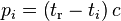 , as
, as
 .
.
These equations can be solved by algebraic or numerical methods.
Least squares method[edit]
When more than four satellites are available, the calculation can use the four best or more than four, considering number of channels, processing capability, and geometric dilution of precision (GDOP). Using more than four is an over-determined system of equations with no unique solution, which must be solved by a least-squares method.[100] Errors can be estimated through the residuals. With each combination of four or more satellites, a GDOP factor can be calculated, based on the relative sky directions of the satellites used.[101] The location is expressed in a specific coordinate system or as latitude and longitude, using the WGS 84 geodetic datum or a country-specific system.[102]

Bancroft's method[edit]
Bancroft's method involves an algebraic as opposed to numerical method and can be used for the case of four or more satellites.[103][104] Bancroft's method provides one or two solutions for the four unknowns. However when there are two solutions, only one of these two solutions will be a near earth sensible solution. When there are four satellites, we use the inverse of the B matrix in section 2 of.[104] If there are more than four satellites then we use the Generalized inverse (i.e. the pseudoinverse) of the B matrix since in this case the B matrix is no longer square.
Error sources and analysis[edit]
GPS error analysis examines the sources of errors in GPS results and the expected size of those errors. GPS makes corrections for receiver clock errors and other effects but there are still residual errors which are not corrected. Sources of error include signal arrival time measurements, numerical calculations, atmospheric effects, ephemeris and clock data, multipath signals, and natural and artificial interference. The magnitude of the residual errors resulting from these sources is dependent on geometric dilution of precision.
Artificial errors may result from jamming devices and threaten ships and aircraft.[105]
Accuracy enhancement and surveying[edit]
|
|
This article duplicates, in whole or part, the scope of other article(s) or section(s). (November 2013) |
Augmentation[edit]
Integrating external information into the calculation process can materially improve accuracy. Such augmentation systems are generally named or described based on how the information arrives. Some systems transmit additional error information (such as clock drift, ephemera, or ionospheric delay), others characterize prior errors, while a third group provides additional navigational or vehicle information.
Examples of augmentation systems include the Wide Area Augmentation System (WAAS), European Geostationary Navigation Overlay Service (EGNOS), Differential GPS, Inertial Navigation Systems (INS) and Assisted GPS.
Precise monitoring[edit]
Accuracy can be improved through precise monitoring and measurement of existing GPS signals in additional or alternate ways.
The largest remaining error is usually the unpredictable delay through the ionosphere. The spacecraft broadcast ionospheric model parameters, but some errors remain. This is one reason GPS spacecraft transmit on at least two frequencies, L1 and L2. Ionospheric delay is a well-defined function of frequency and the total electron content (TEC) along the path, so measuring the arrival time difference between the frequencies determines TEC and thus the precise ionospheric delay at each frequency.
Military receivers can decode the P(Y) code transmitted on both L1 and L2. Without decryption keys, it is still possible to use a codeless technique to compare the P(Y) codes on L1 and L2 to gain much of the same error information. However, this technique is slow, so it is currently available only on specialized surveying equipment. In the future, additional civilian codes are expected to be transmitted on the L2 and L5 frequencies (see GPS modernization). Then all users will be able to perform dual-frequency measurements and directly compute ionospheric delay errors.
A second form of precise monitoring is called Carrier-Phase Enhancement (CPGPS). This corrects the error that arises because the pulse transition of the PRN is not instantaneous, and thus the correlation (satellite-receiver sequence matching) operation is imperfect. CPGPS uses the L1 carrier wave, which has a period of  , which is about one-thousandth of the C/A Gold code bit period of
 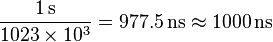 , to act as an additional clock signal and resolve the uncertainty. The phase difference error in the normal GPS amounts to 2–3 metres (6.6–9.8 ft) of ambiguity. CPGPS working to within 1% of perfect transition reduces this error to 3 centimeters (1.2 in) of ambiguity. By eliminating this error source, CPGPS coupled with DGPS normally realizes between 20–30 centimetres (7.9–12 in) of absolute accuracy.
Relative Kinematic Positioning (RKP) is a third alternative for a precise GPS-based positioning system. In this approach, determination of range signal can be resolved to a precision of less than 10 centimeters (3.9 in). This is done by resolving the number of cycles that the signal is transmitted and received by the receiver by using a combination of differential GPS (DGPS) correction data, transmitting GPS signal phase information and ambiguity resolution techniques via statistical tests—possibly with processing in real-time (real-time kinematic positioning, RTK).
Timekeeping [edit]
Leap seconds[edit]
While most clocks derive their time from Coordinated Universal Time (UTC), the atomic clocks on the satellites are set to GPS time (GPST; see the page of United States Naval Observatory). The difference is that GPS time is not corrected to match the rotation of the Earth, so it does not contain leap seconds or other corrections that are periodically added to UTC. GPS time was set to match UTC in 1980, but has since diverged. The lack of corrections means that GPS time remains at a constant offset with International Atomic Time (TAI) (TAI − GPS = 19 seconds). Periodic corrections are performed to the on-board clocks to keep them synchronized with ground clocks.[106]
The GPS navigation message includes the difference between GPS time and UTC. As of July 2012, GPS time is 16 seconds ahead of UTC because of the leap second added to UTC June 30, 2012.[107] Receivers subtract this offset from GPS time to calculate UTC and specific timezone values. New GPS units may not show the correct UTC time until after receiving the UTC offset message. The GPS-UTC offset field can accommodate 255 leap seconds (eight bits).
Accuracy[edit]
GPS time is theoretically accurate to about 14 nanoseconds.[108] However, most receivers lose accuracy in the interpretation of the signals and are only accurate to 100 nanoseconds.[109][110]
Format[edit]
As opposed to the year, month, and day format of the Gregorian calendar, the GPS date is expressed as a week number and a seconds-into-week number. The week number is transmitted as a ten-bit field in the C/A and P(Y) navigation messages, and so it becomes zero again every 1,024 weeks (19.6 years). GPS week zero started at 00:00:00 UTC (00:00:19 TAI) on January 6, 1980, and the week number became zero again for the first time at 23:59:47 UTC on August 21, 1999 (00:00:19 TAI on August 22, 1999). To determine the current Gregorian date, a GPS receiver must be provided with the approximate date (to within 3,584 days) to correctly translate the GPS date signal. To address this concern the modernized GPS navigation message uses a 13-bit field that only repeats every 8,192 weeks (157 years), thus lasting until the year 2137 (157 years after GPS week zero).
Carrier phase tracking (surveying)[edit]
Another method that is used in surveying applications is carrier phase tracking. The period of the carrier frequency multiplied by the speed of light gives the wavelength, which is about 0.19 meters for the L1 carrier. Accuracy within 1% of wavelength in detecting the leading edge reduces this component of pseudorange error to as little as 2 millimeters. This compares to 3 meters for the C/A code and 0.3 meters for the P code.
However, 2 millimeter accuracy requires measuring the total phase—the number of waves multiplied by the wavelength plus the fractional wavelength, which requires specially equipped receivers. This method has many surveying applications.
Triple differencing followed by numerical root finding, and a mathematical technique called least squares can estimate the position of one receiver given the position of another. First, compute the difference between satellites, then between receivers, and finally between epochs. Other orders of taking differences are equally valid. Detailed discussion of the errors is omitted.
The satellite carrier total phase can be measured with ambiguity as to the number of cycles. Let  denote the phase of the carrier of satellite j measured by receiver i at time
  . This notation shows the meaning of the subscripts i, j, and k. The receiver (r), satellite (s), and time (t) come in alphabetical order as arguments of
  and to balance readability and conciseness, let
  be a concise abbreviation. Also we define three functions, :
 , which return differences between receivers, satellites, and time points, respectively. Each function has variables with three subscripts as its arguments. These three functions are defined below. If
  is a function of the three integer arguments, i, j, and k then it is a valid argument for the functions, :, with the values defined as
 ,
, , and
, and .
.
Also if  are valid arguments for the three functions and a and b are constants then
  is a valid argument with values defined as
 ,
, , and
, and .
.
Receiver clock errors can be approximately eliminated by differencing the phases measured from satellite 1 with that from satellite 2 at the same epoch.[111] This difference is designated as 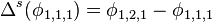
Double differencing[112] computes the difference of receiver 1's satellite difference from that of receiver 2. This approximately eliminates satellite clock errors. This double difference is:

Triple differencing[113] subtracts the receiver difference from time 1 from that of time 2. This eliminates the ambiguity associated with the integral number of wavelengths in carrier phase provided this ambiguity does not change with time. Thus the triple difference result eliminates practically all clock bias errors and the integer ambiguity. Atmospheric delay and satellite ephemeris errors have been significantly reduced. This triple difference is:
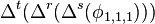
Triple difference results can be used to estimate unknown variables. For example if the position of receiver 1 is known but the position of receiver 2 unknown, it may be possible to estimate the position of receiver 2 using numerical root finding and least squares. Triple difference results for three independent time pairs quite possibly will be sufficient to solve for receiver 2's three position components. This may require the use of a numerical procedure.[114][115] An approximation of receiver 2's position is required to use such a numerical method. This initial value can probably be provided from the navigation message and the intersection of sphere surfaces. Such a reasonable estimate can be key to successful multidimensional root finding. Iterating from three time pairs and a fairly good initial value produces one observed triple difference result for receiver 2's position. Processing additional time pairs can improve accuracy, overdetermining the answer with multiple solutions. Least squares can estimate an overdetermined system. Least squares determines the position of receiver 2 which best fits the observed triple difference results for receiver 2 positions under the criterion of minimizing the sum of the squares.
Regulatory spectrum issues concerning GPS receivers[edit]
In the United States, GPS receivers are regulated under the Federal Communications Commission's (FCC) Part 15 rules. As indicated in the manuals of GPS-enabled devices sold in the United States, as a Part 15 device, it "must accept any interference received, including interference that may cause undesired operation."[116] With respect to GPS devices in particular, the FCC states that GPS receiver manufacturers, "must use receivers that reasonably discriminate against reception of signals outside their allocated spectrum.".[117] For the last 30 years, GPS receivers have operated next to the Mobile Satellite Service band, and have discriminated against reception of mobile satellite services, such as Inmarsat, without any issue.
The spectrum allocated for GPS L1 use by the FCC is 1559 to 1610 MHz, while the spectrum allocated for satellite-to-ground use owned by Lightsquared is the Mobile Satellite Service band.[118] Since 1996, the FCC has authorized licensed use of the spectrum neighboring the GPS band of 1525 to 1559 MHz to the Virginia company LightSquared. on March 1, 2001, the FCC received an application from LightSquared's predecessor, Motient Services to use their allocated frequencies for an integrated satellite-terrestrial service.[119] In 2002, the U.S. GPS Industry Council came to an out-of-band-emissions (OOBE) agreement with LightSquared to prevent transmissions from LightSquared's ground-based stations from emitting transmissions into the neighboring GPS band of 1559 to 1610 MHz.[120] In 2004, the FCC adopted the OOBE agreement in its authorization for LightSquared to deploy a ground-based network ancillary to their satellite system - known as the Ancillary Tower Components (ATCs) - "We will authorize MSS ATC subject to conditions that ensure that the added terrestrial component remains ancillary to the principal MSS offering. We do not intend, nor will we permit, the terrestrial component to become a stand-alone service." [121] This authorization was reviewed and approved by the U.S. Interdepartment Radio Advisory Committee, which includes the U.S. Department of Agriculture, U.S. Air Force, U.S. Army, U.S. Coast Guard, Federal Aviation Administration, National Aeronautics and Space Administration, Interior, and U.S. Department of Transportation.[122]
In January 2011, the FCC conditionally authorized LightSquared's wholesale customers, such as Best Buy, Sharp, and C Spire, to be able to only purchase an integrated satellite-ground-based service from LightSquared and re-sell that integrated service on devices that are equipped to only use the ground-based signal using LightSquared's allocated frequencies of 1525 to 1559 MHz.[123] In December 2010, GPS receiver manufacturers expressed concerns to the FCC that LightSquared's signal would interfere with GPS receiver devices[124] although the FCC's policy considerations leading up to the January 2011 order did not pertain to any proposed changes to the maximum number of ground-based LightSquared stations or the maximum power at which these stations could operate. The January 2011 order makes final authorization contingent upon studies of GPS interference issues carried out by a LightSquared led working group along with GPS industry and Federal agency participation.
GPS receiver manufacturers design GPS receivers to use spectrum beyond the GPS-allocated band. In some cases, GPS receivers are designed to use up to 400 MHz of spectrum in either direction of the L1 frequency of 1575.42 MHz, because mobile satellite services in those regions are broadcasting from space to ground, and at power levels commensurate with mobile satellite services.[125] However, as regulated under the FCC's Part 15 rules, GPS receivers are not warranted protection from signals outside GPS-allocated spectrum.[117] This is why GPS operates next to the Mobile Satellite Service band, and also why the Mobile Satellite Service band operates next to GPS. The symbiotic relationship of spectrum allocation ensures that users of both bands are able to operate cooperatively and freely.
The FCC adopted rules in February 2003 that allowed Mobile Satellite Service (MSS) licensees such as LightSquared to construct a small number of ancillary ground-based towers in their licensed spectrum to "promote more efficient use of terrestrial wireless spectrum."[126] In those 2003 rules, the FCC stated "As a preliminary matter, terrestrial [Commercial Mobile Radio Service (“CMRS”)] and MSS ATC are expected to have different prices, coverage, product acceptance and distribution; therefore, the two services appear, at best, to be imperfect substitutes for one another that would be operating in predominately different market segments. . . . MSS ATC is unlikely to compete directly with terrestrial CMRS for the same customer base . . .". In 2004, the FCC clarified that the ground-based towers would be ancillary, noting that "We will authorize MSS ATC subject to conditions that ensure that the added terrestrial component remains ancillary to the principal MSS offering. We do not intend, nor will we permit, the terrestrial component to become a stand-alone service." [127] In July 2010, the FCC stated that it expected LightSquared to use its authority to offer an integrated satellite-terrestrial service to "provide mobile broadband services similar to those provided by terrestrial mobile providers and enhance competition in the mobile broadband sector."[128] However, GPS receiver manufacturers have argued that LightSquared's licensed spectrum of 1525 to 1559 MHz was never envisioned as being used for high-speed wireless broadband based on the 2003 and 2004 FCC ATC rulings making clear that the Ancillary Tower Component (ATC) would be, in fact, ancillary to the primary satellite component.[129] To build public support of efforts to continue the 2004 FCC authorization of LightSquared's ancillary terrestrial component vs. a simple ground-based LTE service in the Mobile Satellite Service band, GPS receiver manufacturer Trimble Navigation Ltd. formed the "Coalition To Save Our GPS."[130]
The FCC and LightSquared have each made public commitments to solve the GPS interference issue before the network is allowed to operate.[131][132] However, according to Chris Dancy of the Aircraft Owners and Pilots Association, airline pilots with the type of systems that would be affected "may go off course and not even realize it."[133] The problems could also affect the Federal Aviation Administration upgrade to the air traffic control system, United States Defense Department guidance, and local emergency services including 911.[133]
On February 14, 2012, the U.S. Federal Communications Commission (FCC) moved to bar LightSquared's planned national broadband network after being informed by the National Telecommunications and Information Administration (NTIA), the federal agency that coordinates spectrum uses for the military and other federal government entities, that "there is no practical way to mitigate potential interference at this time".[134][135] LightSquared is challenging the FCC's action.
Other systems[edit]

Other satellite navigation systems in use or various states of development include:
- GLONASS – Russia's global navigation system. Fully operational worldwide.
- Galileo – a global system being developed by the European Union and other partner countries, planned to be operational by 2014 (and fully deployed by 2019)
- Beidou – People's Republic of China's regional system, currently limited to Asia and the West Pacific[136]
- COMPASS – People's Republic of China's global system, planned to be operational by 2020[137][138]
- IRNSS – India's regional navigation system, planned to be operational by 2014, covering India and Northern Indian Ocean[139]
- QZSS – Japanese regional system covering Asia and Oceania
'연구하는 인생 > ♣COMPUTER' 카테고리의 다른 글
| μTorrent (0) | 2014.01.29 |
|---|---|
| BitTorrent (0) | 2014.01.29 |
| * Samsung Galaxy Note 3 , SAMSUNG GALAXY S 4 Manual, iPhone 7 (0) | 2014.01.11 |
| Samsung Galaxy Note 3 (0) | 2014.01.11 |
| Samsung Galaxy Note 2, 3 S Pen (0) | 2014.01.11 |